
Dielectric Constant (Dk) and Loss Tangent (Df) Testing Services
Dielectric constant testing for your materials: accurate Dk and loss tangent (Df) measurement, with 5-business-day standard turnaround and rush service available for external clients.
The Intelligent Electromagnetic Sensor Laboratories (iEMSL) at Texas A&M University is a permittivity (dielectric constant, Dk) and loss tangent (Df) testing service for solids, thin films, liquids and semi-solids, covering 10 kHz to 67 GHz, depending on method: from the parallel plate at 10 kHz – 10 MHz to the DAK-TL2 probe at 10 MHz – 67 GHz. Five complementary methods cover that span: Keysight 16451B parallel plate, DAK-TL2 open coaxial probe, WR-90 waveguide transmission line, split-post dielectric resonator (SPDR), and the Fabry-Perot open resonator (FPOR). Dielectric-constant accuracy ranges from ±0.25% with the FPOR to ±5% with the WR-90 waveguide. SPDR testing is available at room temperature or up to 100 °C; every other method is room temperature only. Pricing starts at $300 per sample.
iEMSL offers specialized material characterization services, with the split-post dielectric resonator and Fabry-Perot open resonator methods run in collaboration with QWED and Warsaw University of Technology. We precisely evaluate how materials interact with electromagnetic fields, providing critical data on their properties to support researchers and industries in advanced design and innovation.
What You Get Before You Commit
Before you ship a sample, you can see the pricing, sample requirements and turnaround for every method on this page.
- Published pricing for every method, with its full billing unit, in the method comparison table and the at-a-glance summary below
- Published sample requirements for every method: dimensions and sample state, listed alongside that method
- Standard turnaround of 5 business days, the clock starting when your sample arrives; rush service is available for external clients
- A method recommendation before you are quoted, if you are unsure which of the five fits your material
Our Core Capabilities & Instrumentation
We precisely measure fundamental electromagnetic properties of materials, including complex permittivity (ϵ=ϵ′−jϵ′′), which comprises the dielectric constant (dk or ϵr′ or K) and the loss tangent (df or tanδ=ϵ′′/ϵ′), as well as shielding effectiveness.
We specialize in the characterization of solid dielectrics and semiconductors: printed circuit board substrates, laminates, insulators, polymers, composites and thin films. For magnetic materials and for lossy or lightly doped samples, complex permeability and shielding effectiveness are available on the WR-90 fixture. Accurate analysis of these properties is vital for product development, quality control, and material selection.
What We Measure: Material Categories and Capabilities
Solid Dielectrics
Laminates, substrates, polymers, ceramics and composites: the insulating materials that set impedance and loss in a high-frequency design.
- Parameters: Dk (dielectric constant), Df (loss tangent)
- Sample form: machined coupons, sheets, discs and plates
- Frequency Coverage: 10 kHz – 67 GHz (method-dependent)
- Methods: parallel plate 10 kHz – 10 MHz, DAK-TL2 10 MHz – 67 GHz, WR-90 8.2–12.4 GHz, SPDR 10 GHz, FPOR 10.2–52.2 GHz
Thin Films and Film-on-Substrate
A coating characterized on the substrate it was deposited on. Send the bare substrate with it: on the FPOR it is charged as one additional single-axis sample, and on the SPDR film-on-substrate carries its own flat rate.
- Parameters: Dk and Df of the film, extracted against the bare substrate
- Sample form: up to 0.95 mm thick on the SPDR, 1 µm – 3 mm on the FPOR
- Frequency Coverage: 10 GHz, and 10.2 – 52.2 GHz
- Methods: SPDR 10 GHz, FPOR 10.2 – 52.2 GHz. The FPOR resolves in-plane anisotropy on both axes
Liquids and Semi-Solids
Solvents, gels, slurries and emulsions, measured by immersing the probe. No resonator at iEMSL accepts a liquid, so this is the method for them.
- Parameters: Dk (dielectric constant), Df (loss tangent)
- Sample form: 10 – 50 mL per sample, or a semi-solid layer 0.1 – 10 mm thick. All liquid samples are returned to you
- Frequency Coverage: 10 MHz – 67 GHz
- Methods: DAK-TL2 open coaxial probe. Not for materials below a Df of 0.001
Semiconductors
Bulk and surface conductivity, and film-on-substrate coatings. Conductivity follows from the measured loss, σ = 2πfε₀ε’ tan δ, so it is derived rather than measured separately and carries no additional charge.
- Parameters: Dk (dielectric constant) and Df (loss tangent), measured
σ (conductivity), ρ (resistivity), Rs (sheet resistance, Ω/sq), derived - Sample form: planar samples, 45 – 90 mm across
- Frequency Coverage: 10 GHz
- Methods: SPDR 10 GHz
Absorbers and Lossy Composites
Carbon-loaded, filled and lightly doped materials, where the loss is the measurement rather than a correction to it.
- Parameters: Dk, Df, and shielding effectiveness
- Sample form: shielding effectiveness needs two specimens, 2 mm and 5 mm, each within 5%
- Frequency Coverage: 10 MHz – 67 GHz by probe, 8.2 – 12.4 GHz by waveguide
- Methods: DAK-TL2 for medium and high loss, WR-90 for shielding effectiveness
Ferromagnetics and Magnetic Materials
Materials with a magnetic response, where permittivity alone does not describe the behaviour.
- Parameters: complex permeability (μr), alongside Dk and Df
- Sample form: machined coupon, 22.81 × 10.11 mm, 1 – 9.7 mm thick
- Frequency Coverage: 8.2 – 12.4 GHz (X-band)
- Methods: WR-90 waveguide, permeability as an add-on
How Is Dielectric Constant Measured?
Dielectric constant is measured by placing a sample in a known electromagnetic structure, a capacitor, a probe aperture, a waveguide or a resonator, and extracting permittivity from how the sample changes a measured quantity: capacitance, a reflection coefficient, transmitted and reflected S-parameters, or a resonant frequency and Q factor. Which method fits depends on frequency, sample form and how lossy the material is: a resonator reads loss from a Q factor and suits low-loss materials far better than a probe does.
- Keysight 16451B parallel plate, 10 kHz – 10 MHz: capacitance and dissipation factor of a solid clamped between electrodes, supporting ASTM D150
- DAK-TL2 open coaxial probe, 10 MHz – 67 GHz: permittivity from the reflection at the probe aperture, for solids, liquids and semi-solids; not suited to materials below a Df of 0.001
- WR-90 waveguide, 8.2 – 12.4 GHz: transmission and reflection S-parameters of a solid sample filling the waveguide, supporting ASTM D5568-22a
- Split-post dielectric resonator (SPDR), 10 GHz: the shift in resonant frequency and Q factor when a thin sheet is inserted
- Fabry-Perot open resonator (FPOR), 10.2 – 52.2 GHz: resonant frequency and Q of an open resonator with a large, flat sample inserted
Dielectric Constant Testing Systems
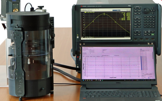
Our measurements utilize advanced Keysight PNA-X (up to 26.5 GHz) and Rohde & Schwarz ZVA (up to 67 GHz) vector network analyzers. Commercial software and our own extraction tools give precise control over the measurement and the parameters we report.
Our services leverage five primary measurement systems, each optimized for specific material types and frequency ranges. Refer to the table below for a quick comparison:


Keysight 16451B Parallel Plate
Frequency Range:
10 kHz – 10 MHz
Sample Requirements:
Diameter: 10 – 56 mm
Thickness: up to 10 mm
Solid dielectrics only
Temperature:
Room temperature only
Application & Specs:
Supporting the ASTM D150 standard, this is the low-frequency method, reaching well below the microwave bands for Dk and dissipation factor of solid dielectrics.
ASTM D150 parallel plate testing and pricing


DAK-TL2 Open Coaxial Probe
Frequency Range:
10 MHz – 67 GHz
Sample Requirements:
Solids: diameter ≥ 68 mm up to 200 MHz, ≥ 48 mm above 200 MHz
Layer thickness: 0.1 – 10 mm
Liquids: 10 – 50 mL per sample
Temperature:
Room temperature only
Application & Specs:
The broadband method, and the only one here that measures liquids and semi-solids. Dk 1 to 800 and Df 0.001 to 10 in one measurement chain, accuracy typically better than 3%. Best for medium and high loss materials, and liquids.
Below a Df of 0.001 it is outside its range; use the FPOR instead.
DAK-TL2 probe testing and pricing

WR-90 Waveguide Transmission Line
Frequency Range:
8.2 – 12.4 GHz (X-Band)
Sample Requirements:
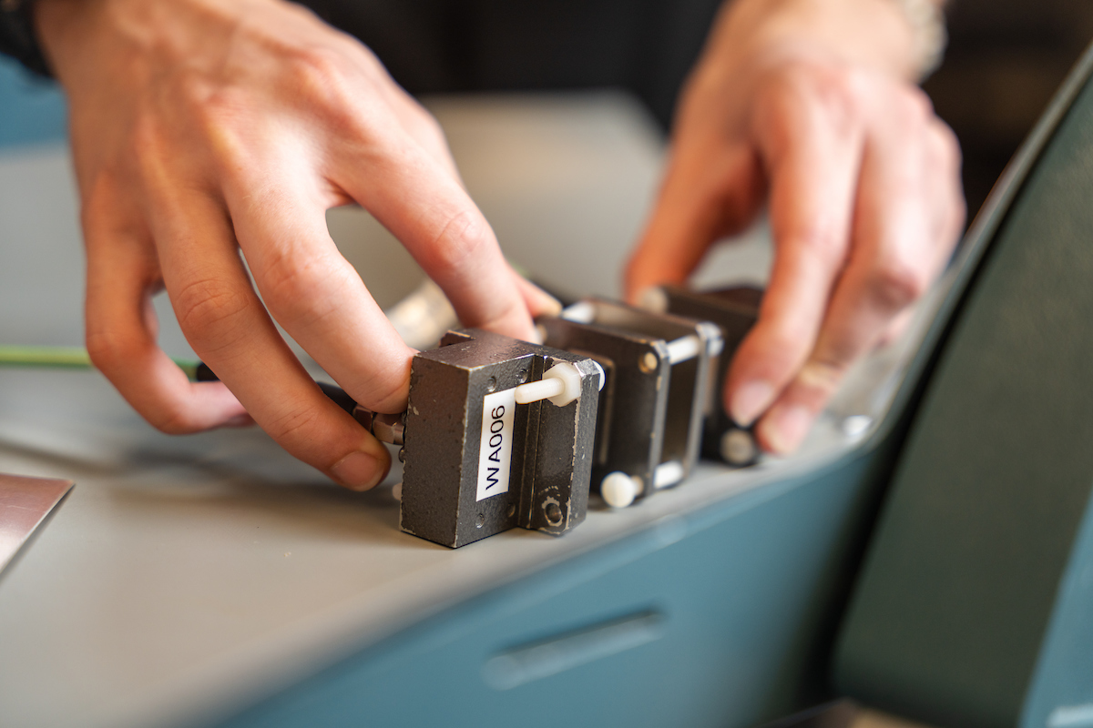
Length: 22.81 mm, Width: 10.11 mm (slip fit),
Thickness: 1–9.7 mm. Three thicknesses recommended.
Temperature:
Room temperature only
Application & Specs:
Supporting the ASTM D5568−22a standard, this broadband technique, best for lossy or medium loss MUTs and machineable solids. It allows high-precision characterization of solid material, measuring dielectric constant (ε’) and loss tangent (tan δ).
Permeability and shielding effectiveness can also be measured on the same fixture.
WR-90 waveguide testing and pricing

Split Post Dielectric Resonator (SPDR)
Frequency:
10 GHz
Sample Requirements:
Length: > 45 mm, Width: 45 – 90 mm, Thickness: up to 0.95 mm
Planar samples with clean edges
Temperature:
Room to 100 °C
Application & Specs:
Supporting the IPC 2.5.5.15 and IEC 61189-2-721 standards, this resonator based method is ideal for accurate characterization of thin dielectrics. Loss tangent resolution reaches ±2×10⁻⁵, suited to extremely low-loss materials. Essential for characterizing ceramics and specialized polymers used in high-Q resonant structures. Characterizes film-on-substrate coatings.
SPDR thin film testing and pricing


Fabry-Perot Open Resonator (FPOR)
Frequency Range:
10.2 – 52.2 GHz
Sample Requirements:
Diameter: 75 – 110 mm (101–109 mm for full range), Thickness: 1 µm – 3 mm
If anisotropic, specify in-plane axes
Temperature:
Room Temperature
Application & Specs:
Ideal for non-destructive, non-contact testing of large, flat material samples (e.g., substrates, composites). Offers high Q factor measurements across a wide frequency spectrum. Characterize in-plane anisotropy of dielectric sheets, polymers, glasses.
FPOR wideband testing and pricing
Method Details, Sample Requirements, and Pricing
Keysight 16451B Parallel Plate (10 kHz – 10 MHz)
A solid dielectric is clamped between parallel plate electrodes and its capacitance and loss are measured directly, giving Dk and dissipation factor from 10 kHz to 10 MHz, per ASTM D150, at room temperature. This is the method for frequencies far below the microwave bands the other four cover.
The iEMSL pairs the Keysight 16451B parallel plate fixture with an Agilent 4275A multi-frequency LCR meter.
Samples are solid dielectrics, 10 to 56 mm in diameter and up to 10 mm thick.
DAK-TL2 Open Coaxial Probe (10 MHz – 67 GHz)
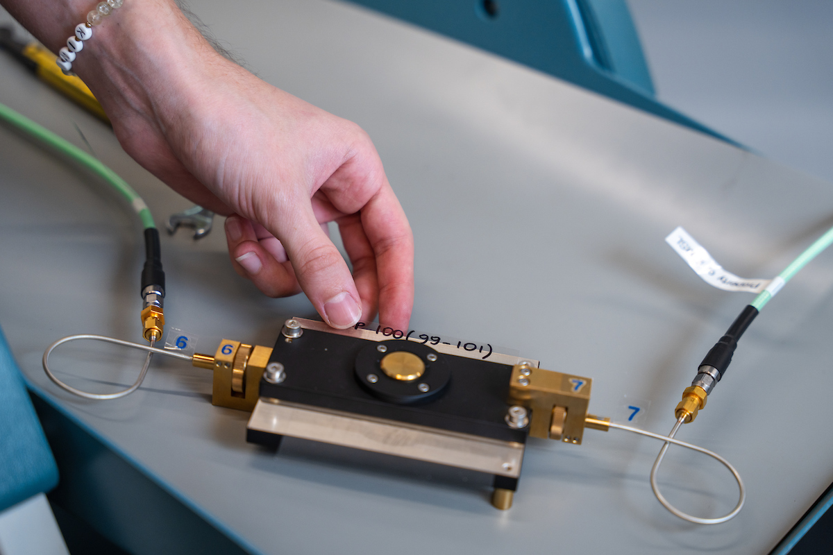
An open-ended coaxial probe is pressed against a sample, or immersed in a liquid, and permittivity is derived from the reflection at the probe aperture. That gives continuous coverage from 10 MHz to 67 GHz in one measurement chain, and the ability to measure liquids and semi-solids at all, which no resonator here offers.
The iEMSL uses the SPEAG DAK-TL2 probe with a Keysight PNA-X or a Rohde & Schwarz ZVA 67 vector network analyzer, selected by band. Dk range 1 to 800, Df range 0.001 to 10, accuracy typically better than 3% and repeatability typically ±1%, at room temperature.
It is the right method for medium and high loss materials and the wrong one for low-loss laminates: a reflection measurement treats small loss as a small perturbation, whereas a resonator reads loss from a Q factor. Below a Df of 0.001 the probe is outside its stated range and the FPOR is the method to use. Liquid samples need a Safety Data Sheet and are all returned to you.
WR-90 Waveguide Transmission Line (8.2 – 12.4 GHz)
For solid, homogenous materials, the iEMSL can measure the complex permittivity (±5% accuracy) in the 8.2 – 12.4 GHz (X-band) range.
The iEMSL utilizes the PNA-X Vector Network Analyzer for S-parameter extraction, and a Nicolson-Ross-Weir extraction algorithm script to visualize your material’s response supporting the ASTM D5568 standard. You must provide a solid material matching the provided waveguide dimensions.
Samples must have rectangular dimensions of 22.81 mm x 10.11 mm, with a thickness of 1–9.7 mm.

Measurement limitations to be aware of:
The transmission line method has inherent thickness sensitivities. The Nicolson-Ross-Weir algorithm has known divergence behavior at certain sample thicknesses (integer multiples of the in-material half-wavelength), which depends on the material’s dielectric constant. Df measurement accuracy also depends on sample thickness: low-loss materials need enough thickness to produce measurable attenuation, while high-loss materials need thin enough samples to keep the transmitted signal above noise. Because the optimal thickness depends on properties you may not know in advance, we strongly recommend submitting multiple sample thicknesses.
Recommended submission:
Provide three samples of the same material at different thicknesses. This lets us cross-check the measurement, avoid NRW divergence regions, and select the optimal thickness for both Dk and Df extraction.
| Material class | Suggested thickness set (mm) |
|---|---|
| Unknown / general purpose | 2, 4, 6 |
| Low-loss polymers (PTFE, PE) | 3, 5, 7 |
| Standard polymers, FR-4 substrates | 2, 3.5, 5 |
| High-Dk ceramics or filled composites | 1.5, 2.5, 4 |
| Lossy / carbon-loaded / absorbers | 1, 1.5, 2 |
If only one sample is available, we accept single submissions but Df accuracy is reduced and the result will be flagged if the thickness happens to land near a divergence region.
Accuracy:
- Dielectric constant (Dk): ±5%
- Loss tangent (Df): ±5% above 1 × 10⁻³, larger below
- Shielding effectiveness: ±1%
Price per Sample:
- Room Temperature: $300 per sample, plus a $500 setup fee per job
What you receive:
- Extracted Dk and Df
- Charts and tables (vs frequency and/or temperature as applicable)
- Raw data (Touchstone files) on request
- Technical Report (for additional charge)
View our example measurements.
Split Post Dielectric Resonator (10 GHz) – in collaboration with QWED
The split post dielectric resonator (SPDR) measures the dielectric constant (Dk) and loss tangent (Df) of thin dielectric sheets. Samples must be planar, with lateral dimensions of 45–90 mm (length ≥ 45 mm, width 45–90 mm) and a thickness of up to 0.95 mm.
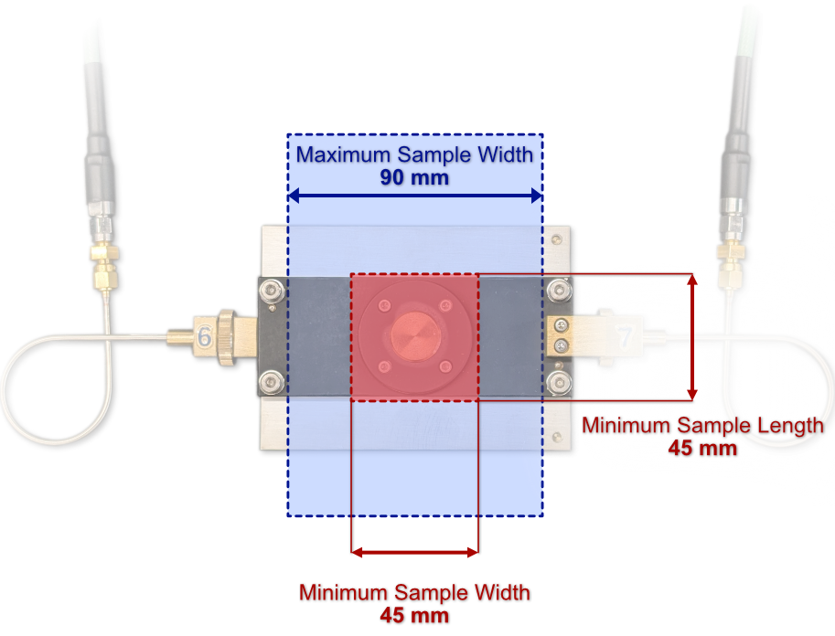
Utilizing the PNA-X Vector Network Analyzer, the iEMSL offers single frequency measurements of the dielectric constant at 10 GHz with the SPDR. Supporting the IPC 2.5.5.15 and IEC 61189-2-721 standards, this resonator based method is ideal for accurate characterization of thin dielectrics. The measurement accuracy for Dielectric constant is Δε/ε = ±(0.0015 + Δh/h) and for Loss tangent: Δtanδ = ±2×10⁻⁵ or ±0.03 × tanδ (higher of the two). For more information, visit QWED.
Price per Sample:
- Room Temperature: $300 per sample
- Up to 100 °C: $500/sample
What you receive:
- Extracted Dk and Df
- Tables (vs temperature as applicable)
- Raw data (CSV) including resonance/Q data on request
- Technical Report (for additional charge)
View our example measurements.
Fabry-Perot Open Resonator (10.2 – 52.2 GHz) – in collaboration with QWED
iEMSL utilizes the ZVA67 Vector Network Analyzer along with the FPOR to offer very high precision for dielectric constant (±0.25%) and loss tangent (±2%) measurements over the wide frequency band of 10.2 – 52.2 GHz, the FPOR is ideal for a wide variety of measurements and precision needs. This also enables In-plane anisotropy testing and climatic compensation is always enabled. Samples should have a diameter between 75 mm and 110 mm and a thickness between 1 µm and 3 mm. The measurement accuracy for Dielectric constant: is ±0.25% (for Dk = 1 – 15) and for Loss tangent: tanδ < 10, ±2% (for Df >5×10⁻⁶).

Thickness & Dk Limitations
This graph illustrates the relationship between a material’s dielectric constant (Dk) and its thickness, defining the measurable and unmeasurable regions for a specific testing method. The green and tan areas represent valid combinations that can be measured, while the two “prohibited zones” indicate combinations that cannot be reliably tested. For Dk < 3, the maximum thickness is 3 mm.
- Green Zone: This is the ideal measurement range, where combinations of Dk and thickness allow for highly reliable and precise results with a low measurement uncertainty of ±0.25%.
- Tan Zone: This area indicates that a measurement can still be obtained, but with a greater uncertainty of ±0.5%.
- Prohibited Zones: These zones represent invalid combinations of Dk and thickness where no reliable data can be acquired.

Thickness & Df Limitations
Limitations are imposed on the maximum loss tangent with respect to thickness. If the material has a very high loss, the resonator curve may not be distinguishable from noise.

Dimension Requirements
To achieve the full frequency range down to 10.2 GHz, the target sample size should be between 101 mm and 109 mm. For rectangular samples, one dimension can be up to 150 mm, but the other must be less than 110 mm.

Room Temperature Pricing (Per Sample):
We measure in four frequency bands across 10.2 to 52.2 GHz, each about 10 GHz wide. Request any single band or the full range, at your choice of precision.
| Precision | Price per band, per axis | Frequency points per band | Full range (4 bands, single axis) |
|---|---|---|---|
| Standard (3 GHz step) | $500 | 4 | $2,000 |
| Advanced (1.5 GHz step) | $800 | 8 | $3,200 |
Frequency bands: Band 1 (10.2 to 20.7 GHz), Band 2 (20.7 to 31.2 GHz), Band 3 (31.2 to 40.2 GHz), Band 4 (40.2 to 52.2 GHz).
Axis Configurations
- Single-Axis: Standard testing included in the base pricing above.
- Dual-Axis (Orthogonal): Measures in-plane anisotropy by running a second measurement cycle. Because this requires a full second cycle, it is billed as an additional sample.
What you receive:
- Extracted parameters (Dk, Df)
- Charts and tables vs frequency
- Raw data (CSV) including and resonance/Q data on request
- Technical Report (for additional charge)
View our example measurements.
Method Comparison: Frequency, Samples, and Pricing
| Method | What it measures | Sample requirements | Price |
|---|---|---|---|
| Parallel Plate Keysight 16451B 10 kHz – 10 MHz |
Dk & dissipation factor of solid dielectrics Supports the ASTM D150 standard The low-frequency method, below the microwave bands |
Diameter: 10 – 56 mm Thickness: up to 10 mm Solid dielectrics only |
Room Temperature: $500/sample |
| Open Coaxial Probe SPEAG DAK-TL2 10 MHz – 67 GHz |
Dk & Df of solids, semi-solids and liquids The only method here that measures liquids Medium and high loss materials; not for Df below 0.001 |
Solids: diameter ≥ 68 mm up to 200 MHz, ≥ 48 mm above Thickness: 0.1 – 10 mm Liquids: 10 – 50 mL |
Room Temperature: $400/sample/band solid $600/sample/band liquid, semi-solid or powder Full range (9 bands): $3,600 solid / $5,400 liquid, semi-solid or powder |
| Transmission Line WR-90 Waveguide 8.2 – 12.4 GHz (X-band) |
Permittivity & Loss tangent for machineable solids Supports the ASTM D5568−22a standard |
Length: 22.81 mm Width: 10.11 mm Thickness: 1–9.7 mm |
Room Temperature: $300 per sample, plus a $500 setup fee per job Shielding effectiveness: same rate, two specimens required Complex permeability: +$200 per sample |
| Split Post Dielectric Resonator (SPDR) 10 GHz |
Complex permittivity of dielectric sheets Supports IPC 2.5.5.15 & IEC 61189-2-721 standards Characterizes film-on-substrate coatings by tracking tiny shifts in resonance frequency and Q-factor |
Length: > 45 mm Width: 45 – 90 mm Thickness: up to 0.95 mm |
Room Temperature: $300 per sample Up to 100 °C: $500/sample Film on a substrate: $500/sample |
| Fabry-Perot Open Resonator (FPOR) 10.2 – 52.2 GHz |
Wideband complex permittivity In-plane anisotropy of dielectric sheets, polymers, glasses Characterizes film-on-substrate coatings |
Diameter: 75–110 mm (101–109 mm for full range; 105 mm ideal) Thickness: 1 µm – 3 mm (Thinner is better) |
Room Temperature: Standard, 3 GHz step: $500/band/axis (4 points) Advanced, 1.5 GHz step: $800/band/axis (8 points) Full range (4 bands, single axis): $2,000 / $3,200 |
At a glance: standard turnaround is 5 business days from receipt of your sample, with rush service available for external clients. WR-90 and SPDR testing is $300 per sample at room temperature; WR-90 also carries a $500 setup fee per job. SPDR also runs up to 100 °C at $500 per sample; WR-90 is room temperature only. FPOR starts at $500 per frequency band per axis. The 16451B parallel plate is $500 per sample. The DAK-TL2 coaxial probe is $400 per sample per band for solids, $600 for liquids, semi-solids and powders. Every method is room temperature only except SPDR. Methods support ASTM D5568-22a, ASTM D150, IPC 2.5.5.15, and IEC 61189-2-721. Texas A&M researchers receive a 50% reduction on listed prices.
Frequently Asked Questions
What is the difference between dielectric constant (Dk) and loss tangent (Df)?
Both come from a material’s complex permittivity, ε = ε′ − jε″. The dielectric constant (Dk, εr′) is the real part: how much electromagnetic energy the material stores. The loss tangent (Df, tanδ = ε″/ε′) is the ratio of energy dissipated to energy stored, i.e. how lossy the material is at a given frequency. Low-loss substrates for high-frequency electronics need both a stable Dk and a low Df.
Which measurement method is right for my material?
It depends on your sample and frequency range. The Keysight 16451B parallel plate (10 kHz – 10 MHz) is the low-frequency method for solid dielectrics and supports ASTM D150. The DAK-TL2 open coaxial probe (10 MHz – 67 GHz) covers the widest range and is the only primary method that takes liquids and semi-solids, though below a Df of 0.001 it is out of range. The WR-90 waveguide transmission line (8.2–12.4 GHz) suits machineable solids and supports ASTM D5568-22a. The split-post dielectric resonator (SPDR) reaches a loss tangent resolution of ±2×10⁻⁵ on thin sheets at a single 10 GHz point, and is the only method that runs to 100 °C. The Fabry-Perot open resonator (FPOR) covers 10.2–52.2 GHz for large, flat samples, is the method for in-plane anisotropy, and is the method for low-loss materials. If you are unsure, request a quote describing your material, and we will recommend a method.
What industry standards do your measurements support?
The WR-90 waveguide method supports ASTM D5568-22a; see ASTM D5568 dielectric constant testing for sample requirements and pricing. The SPDR method supports IPC 2.5.5.15 and IEC 61189-2-721. The parallel plate method supports ASTM D150. The DAK-TL2 coaxial probe is not tied to a published standard.
How much does dielectric testing cost?
WR-90 and SPDR measurements are $300 per sample at room temperature; WR-90 also carries a $500 setup fee per job. SPDR also runs up to 100 °C at $500 per sample; WR-90 is room temperature only. FPOR measurements start at $500 per band per axis (basic) or $800 per band per axis (advanced), with the full 10.2–52.2 GHz range, single axis, at $2,000 (basic) or $3,200 (advanced). The parallel plate is $500 per sample. The DAK-TL2 coaxial probe is $400 per sample per band for solids, $600 for liquids, semi-solids and powders. Texas A&M researchers receive a 50% reduction. See the summary table above for full pricing.
How do I submit a sample for testing?
Start by submitting a request through the Request a Quote form with your material type, target frequency range, and quantity. Prepare samples to the dimensions listed for your chosen method above. For the WR-90 method we recommend submitting three thicknesses of the same material for the most reliable Dk and Df extraction.
What is your turnaround time?
Standard turnaround is 5 business days from receipt of your sample. Rush service is available for time-critical projects. Just request a quote and tell us your deadline.
Can you handle ITAR-controlled or export-controlled work?
Yes. iEMSL accepts ITAR-controlled projects under a Technology Control Plan, administered with the Texas A&M export control office. Tell us your control requirements when you request a quote, before shipping any samples.
Is my material and my data kept confidential?
Yes. An NDA is available on request, and we sign it before you ship anything. Ask for it when you request a quote.
When should I ship my sample?
Wait until you have a quote. We check first that your sample fits the method’s size, thickness and loss limits, which avoids sending material we cannot measure. Shipping instructions come with the quote.
How does payment work, and do we need an account set up first?
The quote form asks for an accounts payable contact at your company. We send that person a customer setup form, and once it comes back you are set up in our system within one to two business days. We invoice after testing is complete, and we accept several payment methods including credit card.
Ready to Measure?
iEMSL is equipped to support your material electrical testing needs. Click below to submit a request to have your material evaluated.