
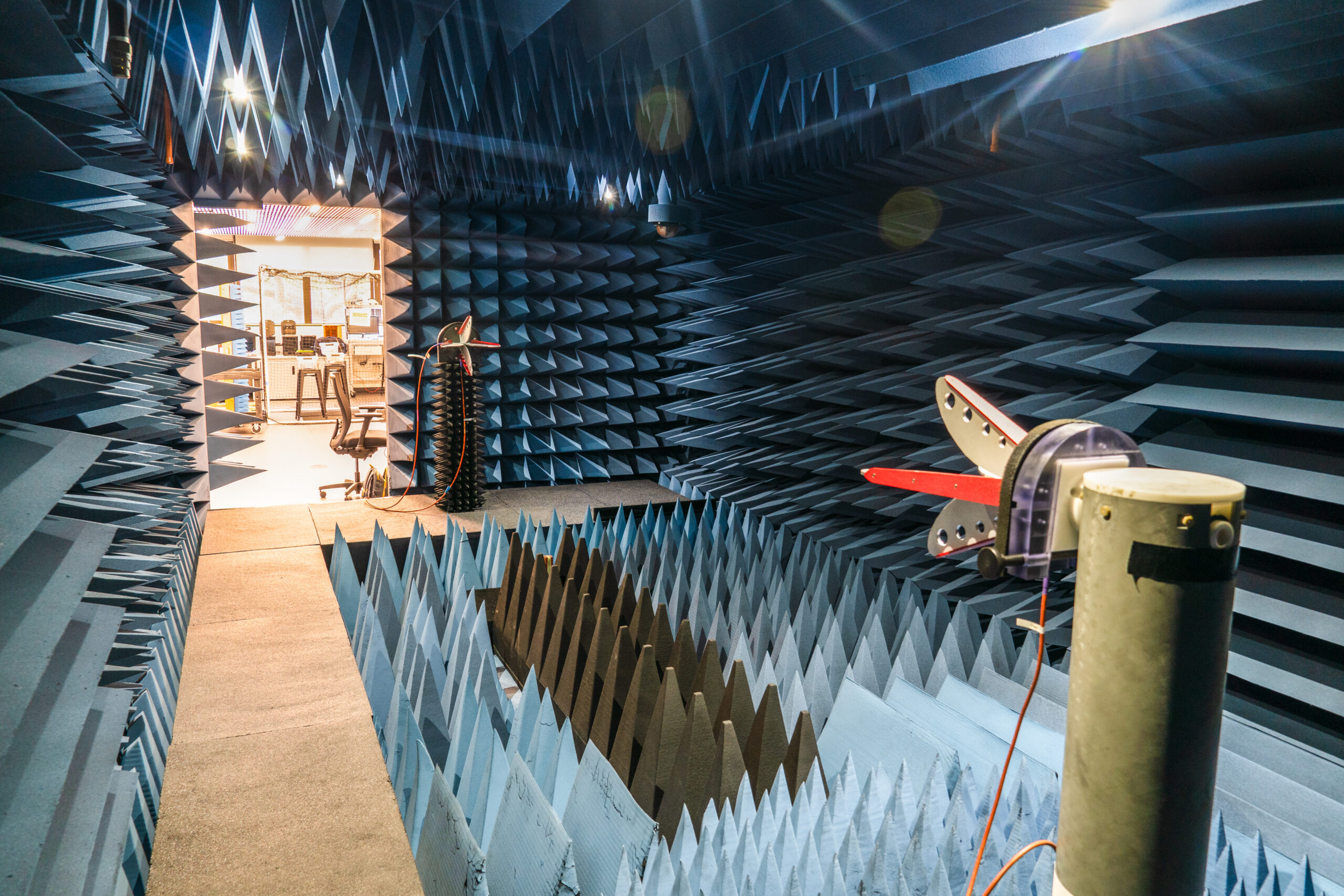
Antenna Measurement Services
Standard turnaround: 3 days
Test the performance of your antenna in the iEMSL’s state-of-the-art anechoic chamber.
Photo credit: Kayla Sidik, 2025
Precision Antenna Measurement — Done Right
From prototype validation to production certification — get accurate, repeatable, publication-ready data in our state-of-the-art anechoic chamber.
Measurement Capabilities
- Gain & Directivity
- Beamwidth
- Cross Polar Discrimination
- Axial Ratio
- Sidelobe Levels
- Envelope Correlation Coefficient
- TRP, TIS, EIRP, and EIS
- Overnight and expedited options available
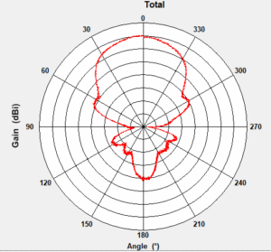
2D Pattern Measurements
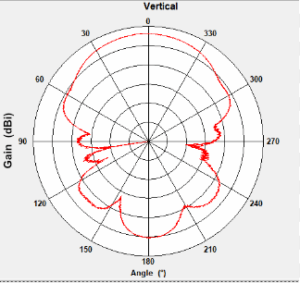
Get fast, high-resolution insight into your antenna’s performance with 2D radiation pattern measurements in our state-of-the-art anechoic chamber for two orthogonal polar cuts (typically elevation/azimuth or E-plane/H-plane cuts)
Our 2D scans provide essential data. You can evaluate beam direction, sidelobe levels, and beamwidth in the E- or H-plane. This lets you quickly fine-tune designs and validate specs without the time commitment of a full 3D sweep.
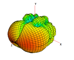
3D Pattern Measurements
For when two slices just aren’t enough—our 3D antenna radiation measurements capture gain and coverage in all directions. We use precision rotary positioning inside our anechoic chamber. This allows us to deliver detailed spatial maps of your antenna’s true radiation shape.
Ideal for high-performance systems, custom designs, and advanced wireless applications, our 3D service provides the gold standard in antenna characterization. In fact, nothing is missed by exploring the entire sphere!
Technical Specs and Capabilities
| Anechoic Chamber Frequency Range | 400 MHz – 140 GHz |
| Standard Sweeps | 400 MHz – 10 GHz 2 GHz – 18 GHz 10 GHz – 40 GHz Custom: >40 GHz (up to 140 GHz) |
| Chamber Internal Dimensions | 24′ x 10′ x 6.5′ |
| Far Field Distance | 16′ |
| Max AUT weight | 34.0 kg (75.0 lb) |
| Scan Geometry | Two-axis, full spherical geometry |
| Scan Range | Up to ±180° pattern coverage |
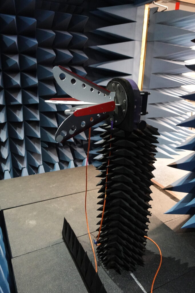
Packages & Pricing
We can measure your passive antenna’s gain patterns in 3D spherical, 2D polar, or even 1D single-direction plot from 400 MHz to 40 GHz.
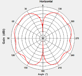
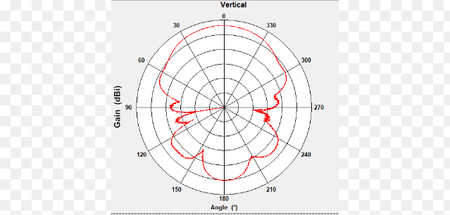
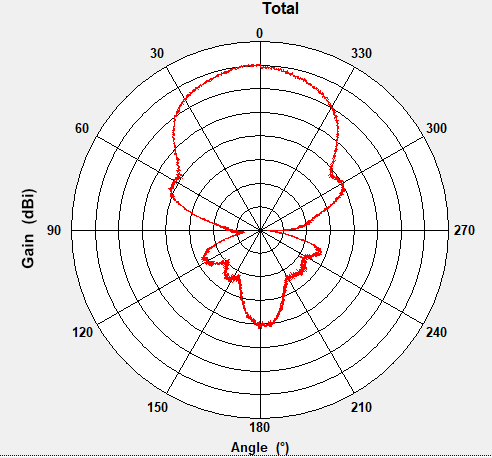
Consequently, you will receive a pattern file for each AUT, This makes the 3D Spherical plots and 2D Polar plots renderable on your machine using the EMQuest Viewer, free software for visualization. You will also receive a spreadsheet that includes Vertical, Horizontal, and Total gain in dBi. This enables easy post-processing and quick creation of custom plots, such as Radiation Efficiency versus frequency, forward gain versus frequency, front-to-back ratios, and more. You will also receive photographs of your antenna in the iEMSL Anechoic Chamber.
The iEMSL offers different levels of measurement precision to suit your needs and budget. Choose from one of the packages below for a fixed price or contact the iEMSL to receive a quote for customized measurement precision.
2D Gain Pattern
| Standard Precision | Advanced Precision | |
|---|---|---|
| Step Size (degrees) | 2° | 1° |
| Number of Frequencies within the standard ranges | Up to 5 | Up to 10 |
| Number of Slices | 2 | 2 |
| Absolute Gain Pattern (dBi) requires Range Calibration | Yes | Yes |
| Lab-provided data export | Spreadsheet + Pattern Files + Photographs | Spreadsheet + Pattern Files + Photographs |
| Price/pattern | $500 First + $400 add’l | $800 First + $600 add’l |
3D Gain Pattern
| Standard Precision | Advanced Precision | |
|---|---|---|
| Step Size (degrees) | 10° | 5° |
| Number of Frequencies within the standard ranges | Up to 5 | Up to 10 |
| Absolute Gain Pattern (dBi) requires Range Calibration | Yes | Yes |
| Radiation Efficiency (dB & %) | No | Yes |
| Lab-provided data export | Spreadsheet + Pattern Files + Photographs | Spreadsheet + Pattern Files + Photographs |
| Price/pattern | $500 First + $400 add’l | $800 First + $600 add’l |
Note: TAMU researchers receive a 50% reduction on the listed prices.
Mounting & Setup
Use our standard mounts hole pattern to avoid delays. View mounting specs →
Additional Measurements
Return Loss & VSWR
Using a vector network analyzer (VNA), we measure return loss before radiation testing to verify matching performance.
S1P Touchstone file included. Full frequency sweep data for import into simulation tools.
Extra Cuts and Frequency Points
Need more data? Add additional polar cuts (E/H-plane, diagonal) or extra frequency points.
Ideal for multi-band antennas or fine-tuning performance across operating bands.
Custom Measurements
We offer a comprehensive suite of custom antenna and electromagnetic measurements. This includes highly precise 3D radiation patterns, captured with a maximum resolution of a 1-degree step size. For active antennas, our testing services cover transmitter patterns, as well as the measurement of both Total Radiated Power (TRP) and Equivalent Isotropically Radiated Power (EIRP) in dBm.
For custom tests, $500 Setup fee is charged in addition $450/hour. Minimum 1-hour charge per use. Use over one hour will be rounded to the nearest 15-minute increment.
Need the Chamber All Day?
$4,500
Exclusive 8-hour access • Full staff support • Priority scheduling • Custom test plans
Frequently Asked Questions
How do I get started testing an antenna in the Anechoic Chamber?
Start by making sure your antenna is within our chamber’s testing capability. We can accommodate passive antennas (with or without LNA) with frequencies between 400 MHz and 40 GHz. To start, make sure your antenna fits our capabilities, then request a measurement by clicking the button at the top or bottom of this webpage.
What kind of information can the iEMSL tell me about my antenna?
We can give you reliable an accurate measures of your antenna’s SWR (standing wave ratio), beam width, directivity, gain, efficiency, and front-to-back ratio. We can also plot your antenna’s radiation pattern as polar (2D) or spherical (3D) plots, and we can even assist in exporting your data to other file formats such as STL or OBJ for better visualization.
How long do the tests take to perform?
Tests vary in duration based on the level of precision needed, and we can provide more information once we learn about your antenna and what kind of tests you’d like to perform. Are you interested in a very basic understanding of the general shape of your antenna’s radiation pattern? A Standard Precision 2D Measurement will only take about 30 minutes from start to finish. If you need high granularity and extremely precise measurements in three dimensions, a Maximum Precision 3D Measurement can take up to 5 or 6 hours to complete.
The level of precision I want is not listed above. What do I do?
Not a problem! Our team is happy to work with you directly to set up customized and specific tests to suit your precision needs. Please request a measurement by clicking the button at the top or bottom of this page to get started!
Ready to Test Your Antenna?
From startups to Fortune 500 — trusted by engineers worldwide.