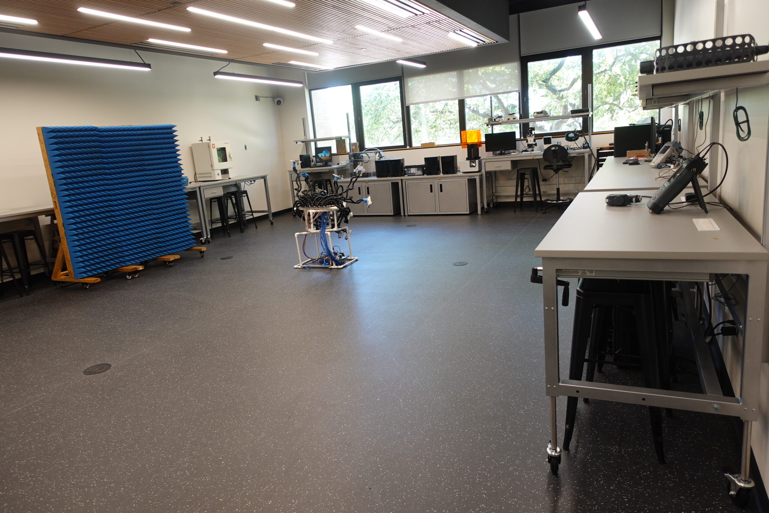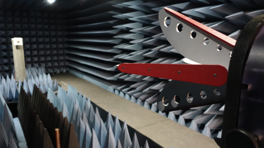

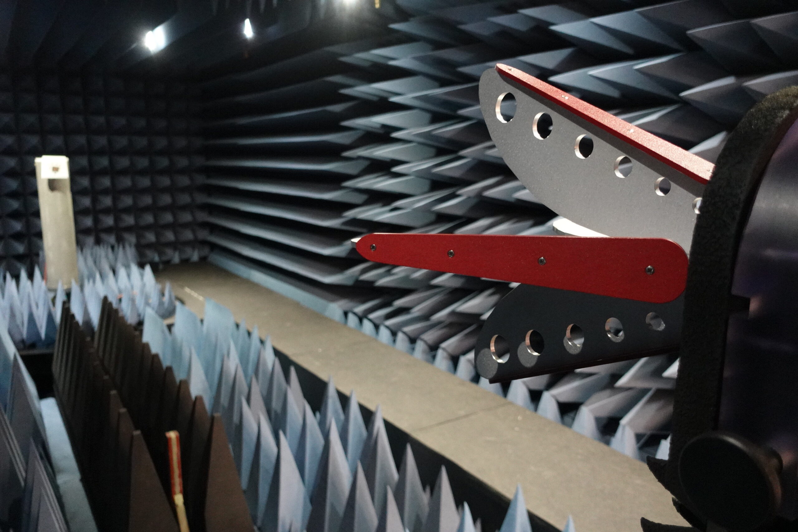
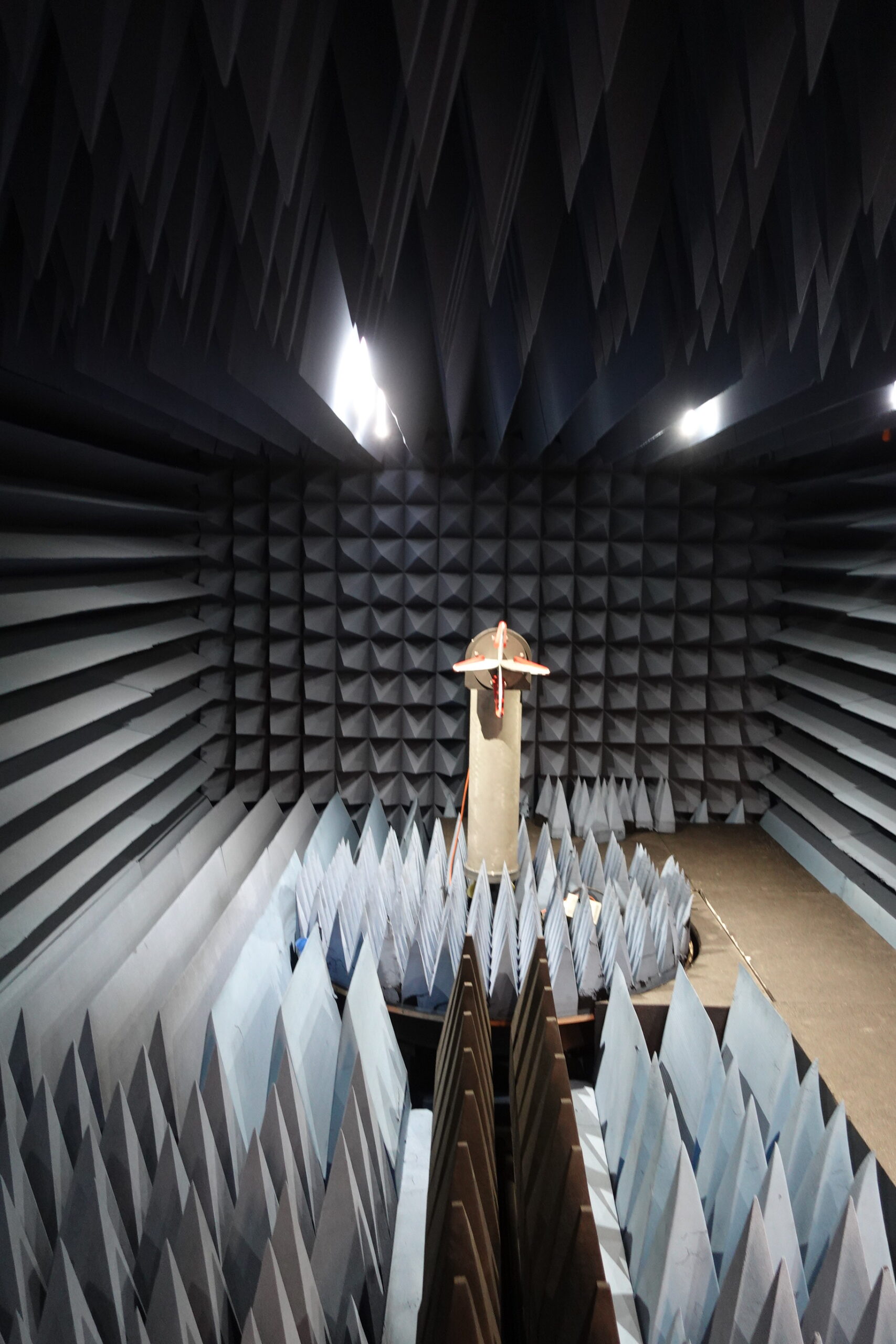
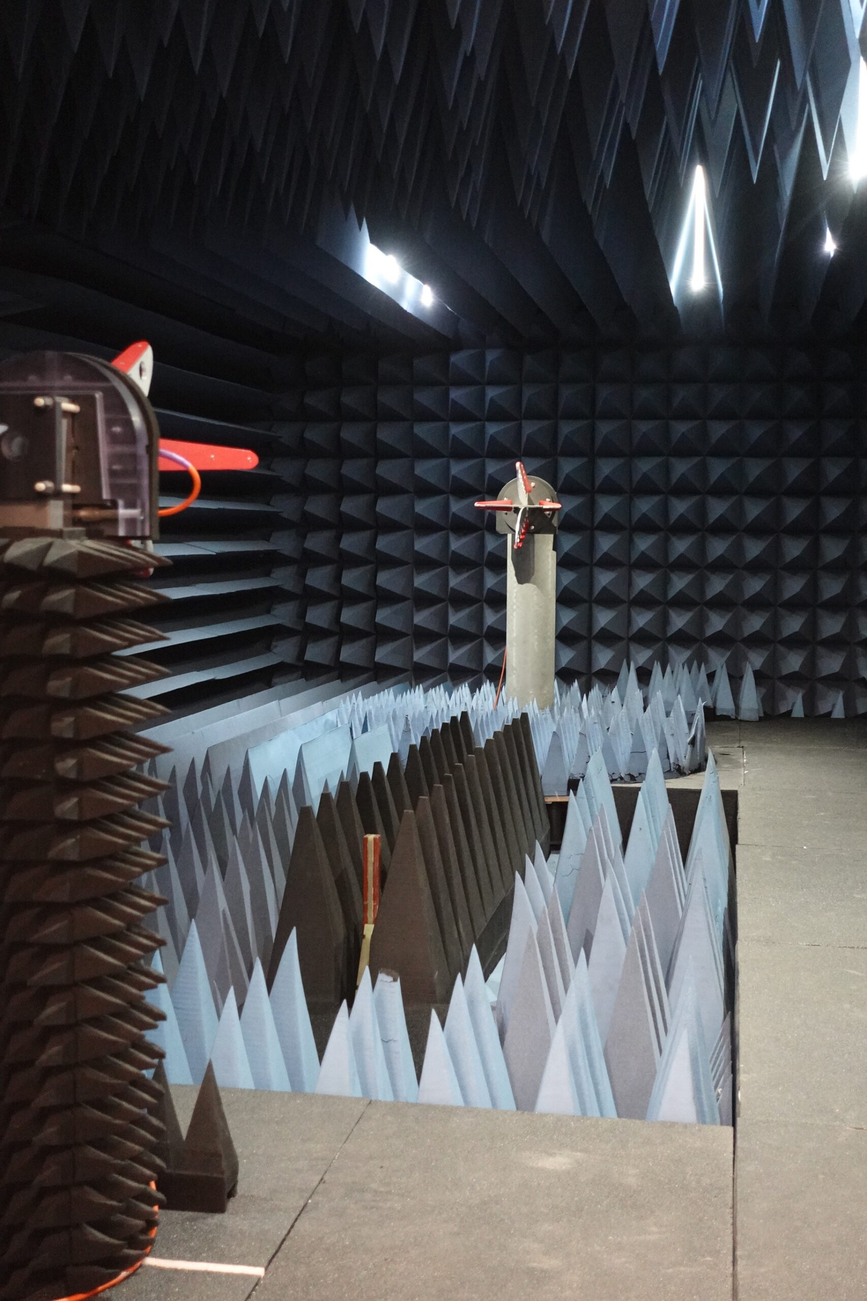
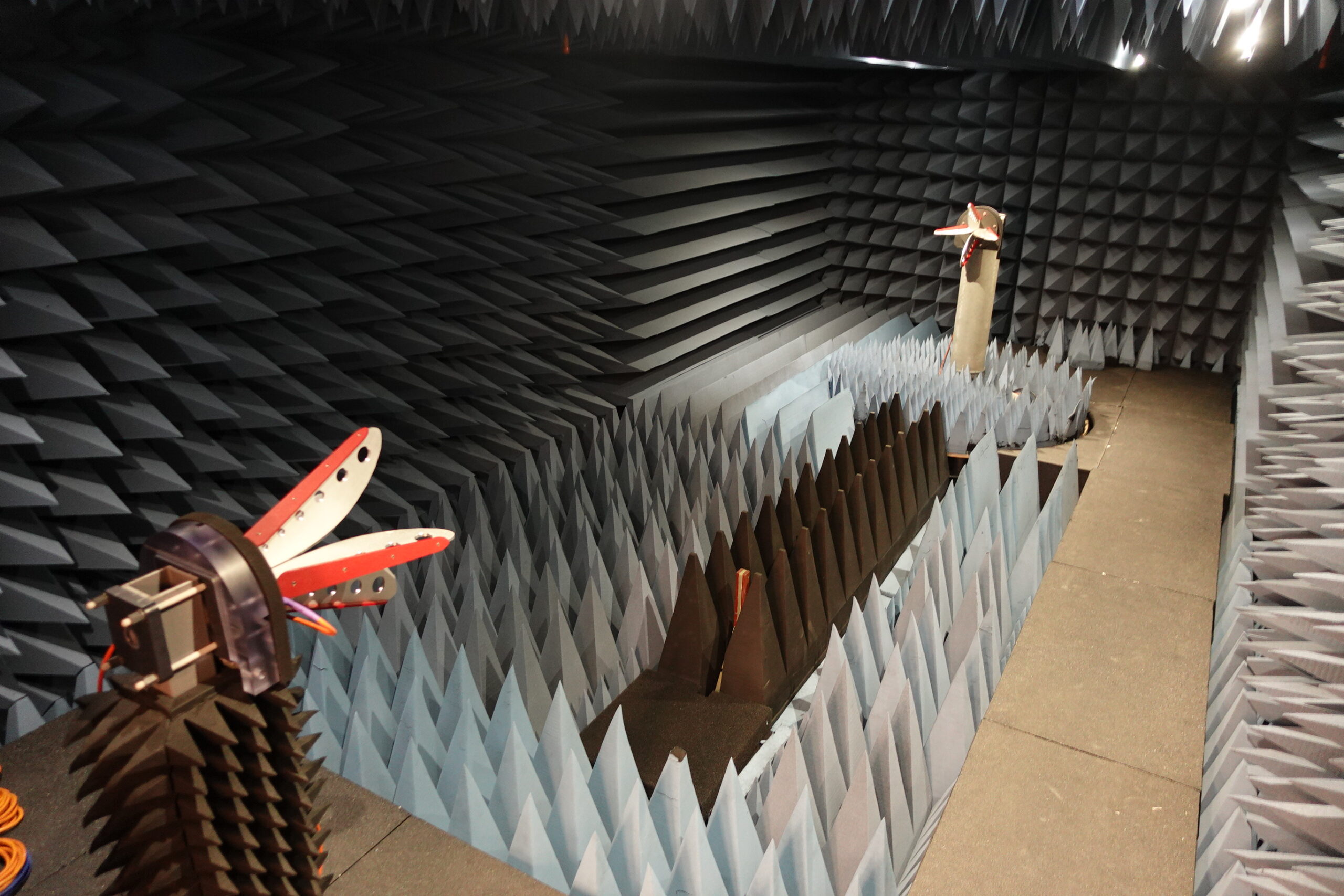
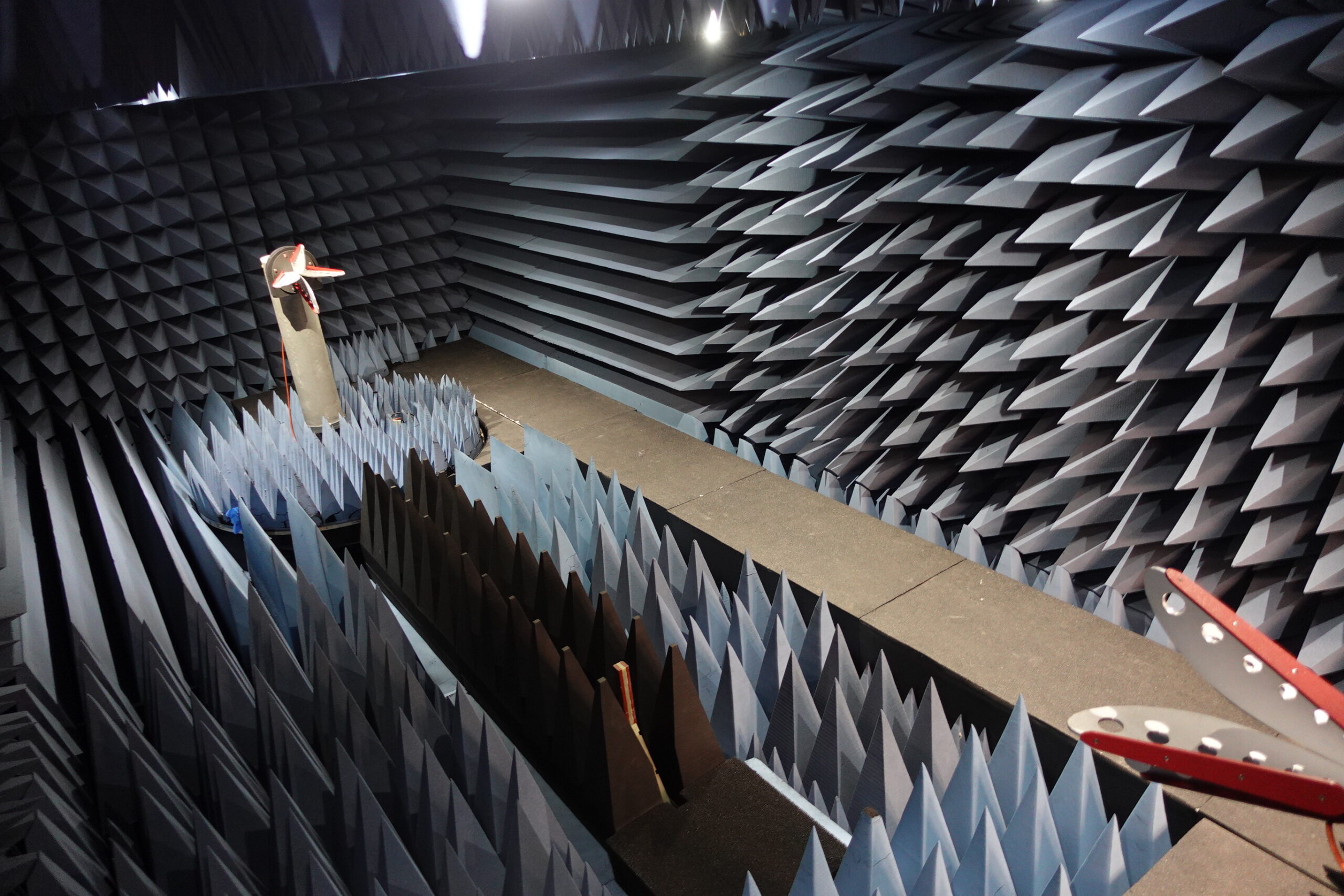
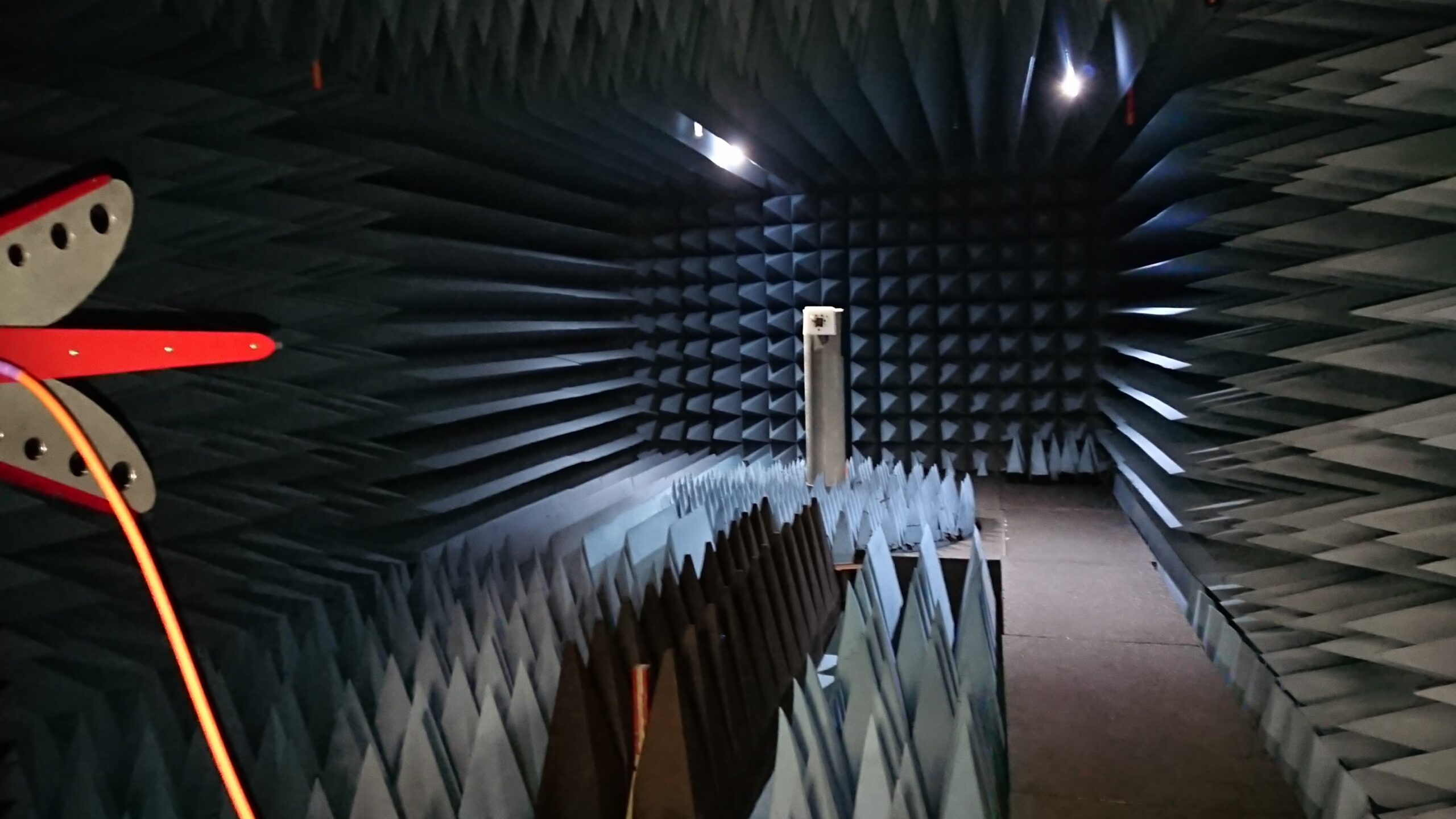
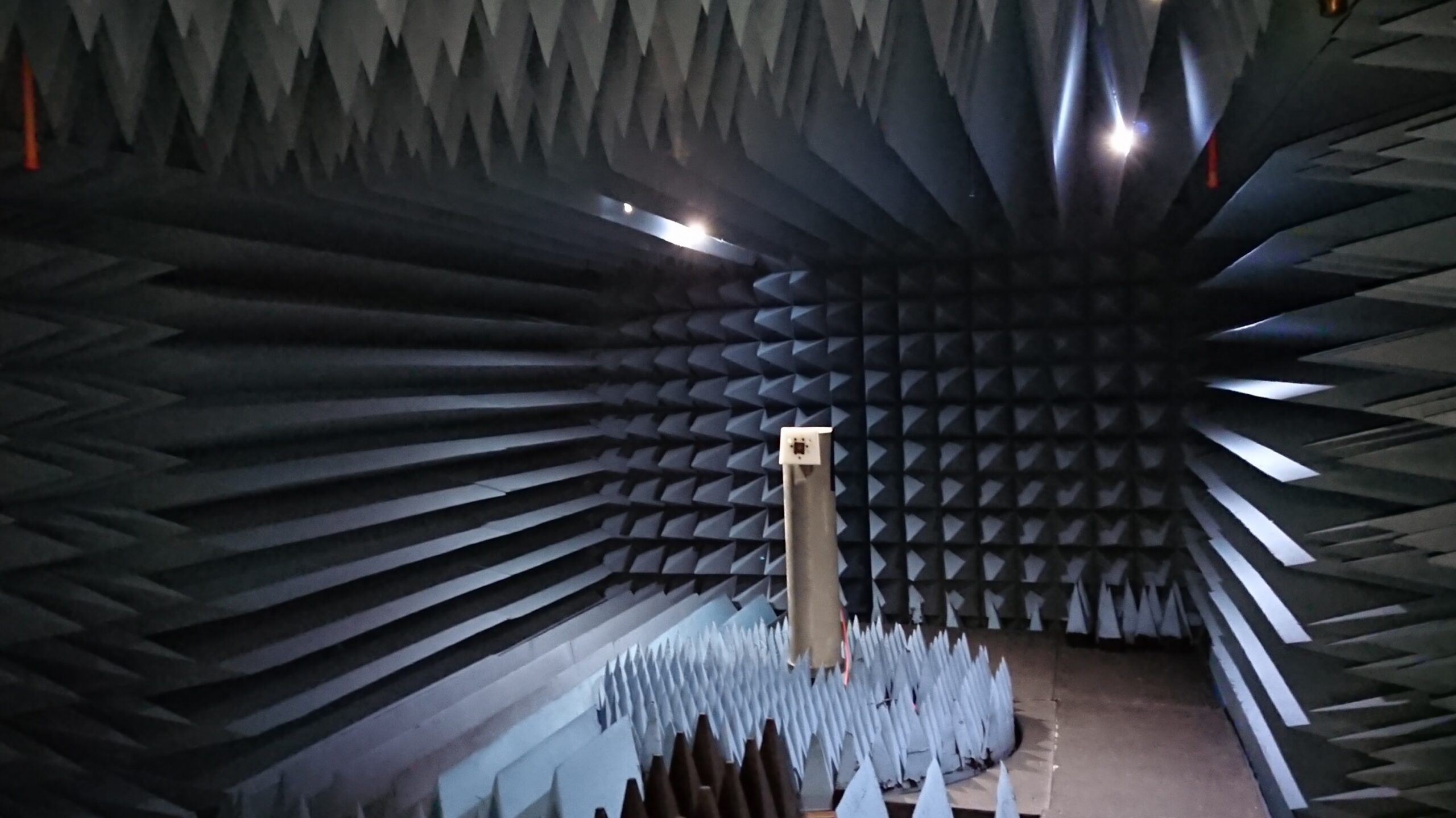
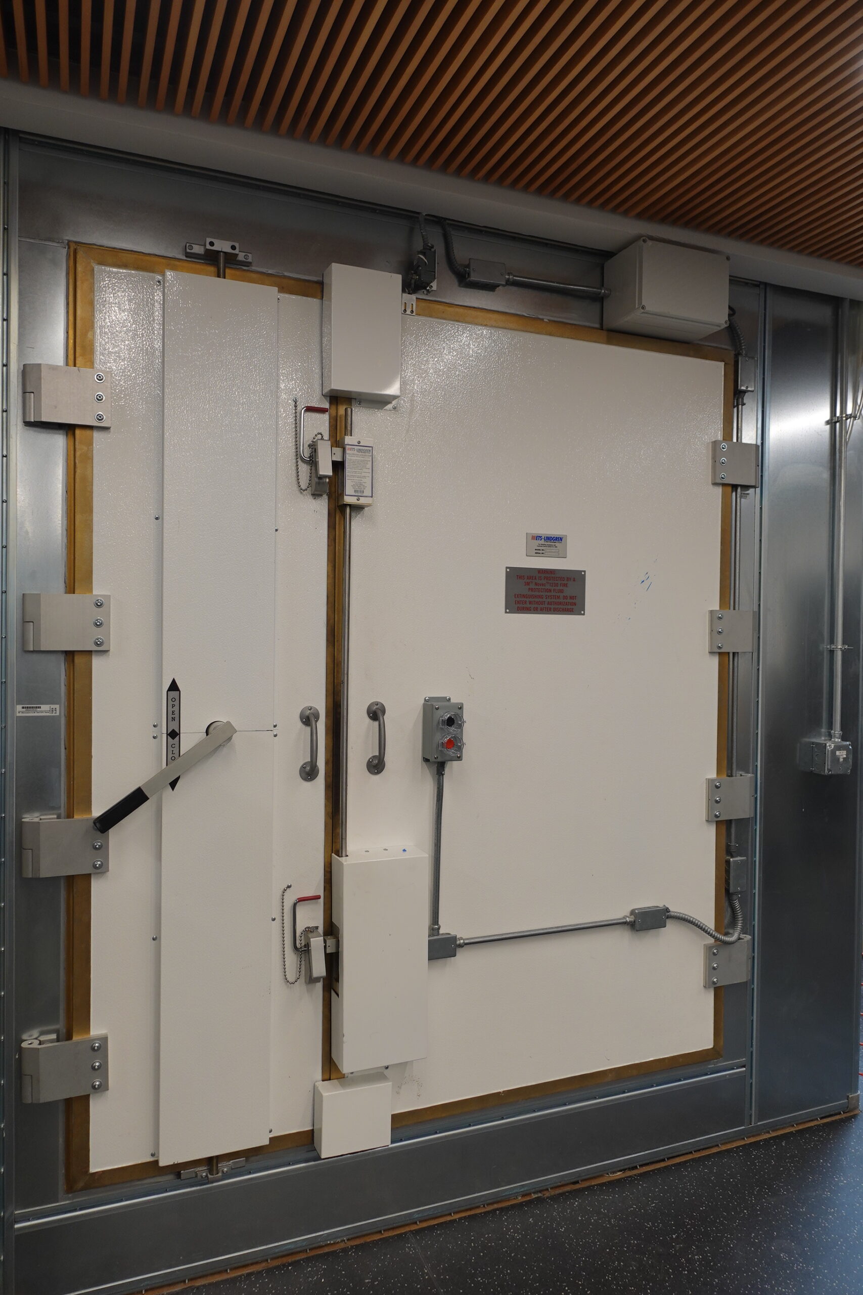
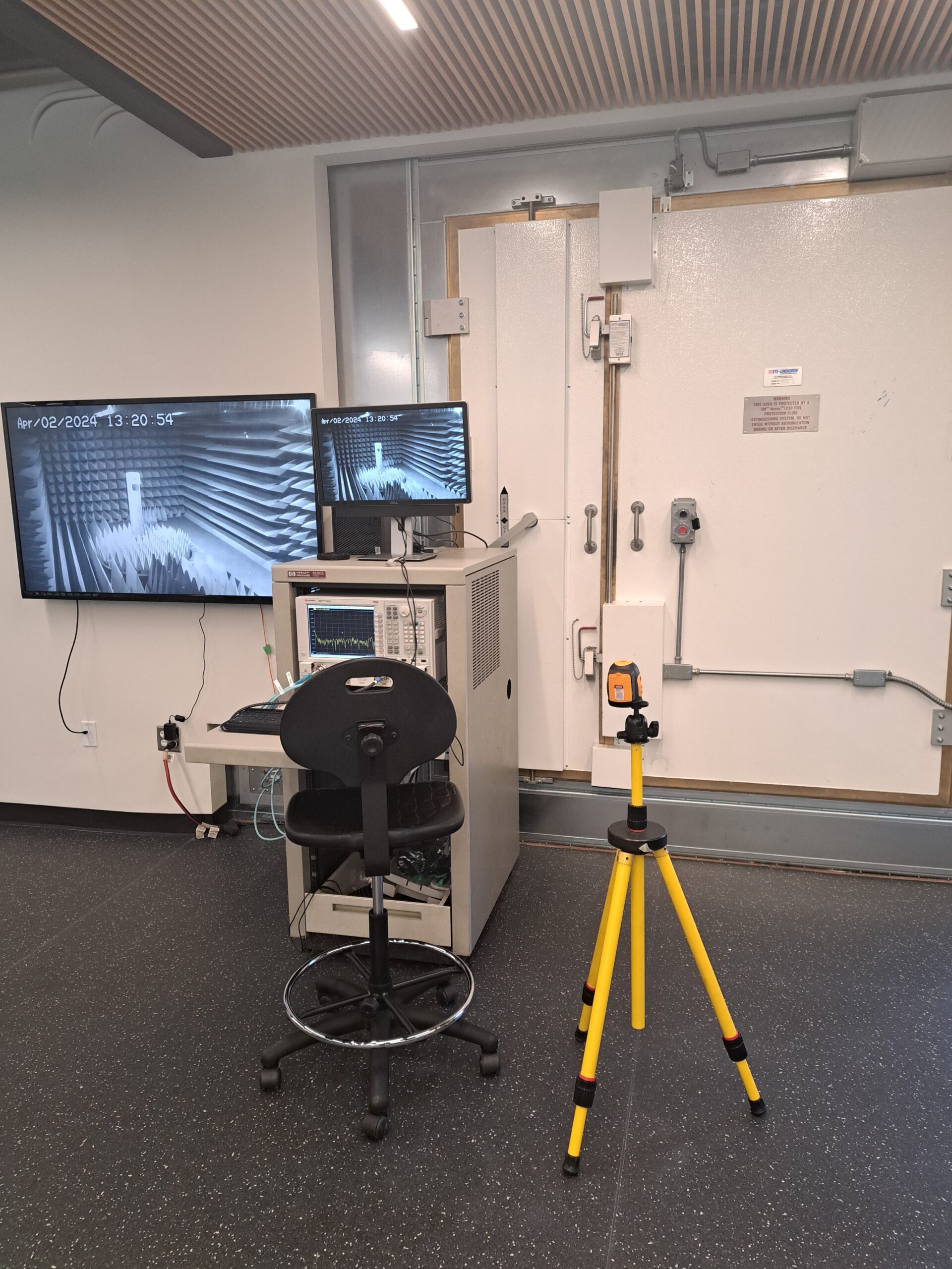
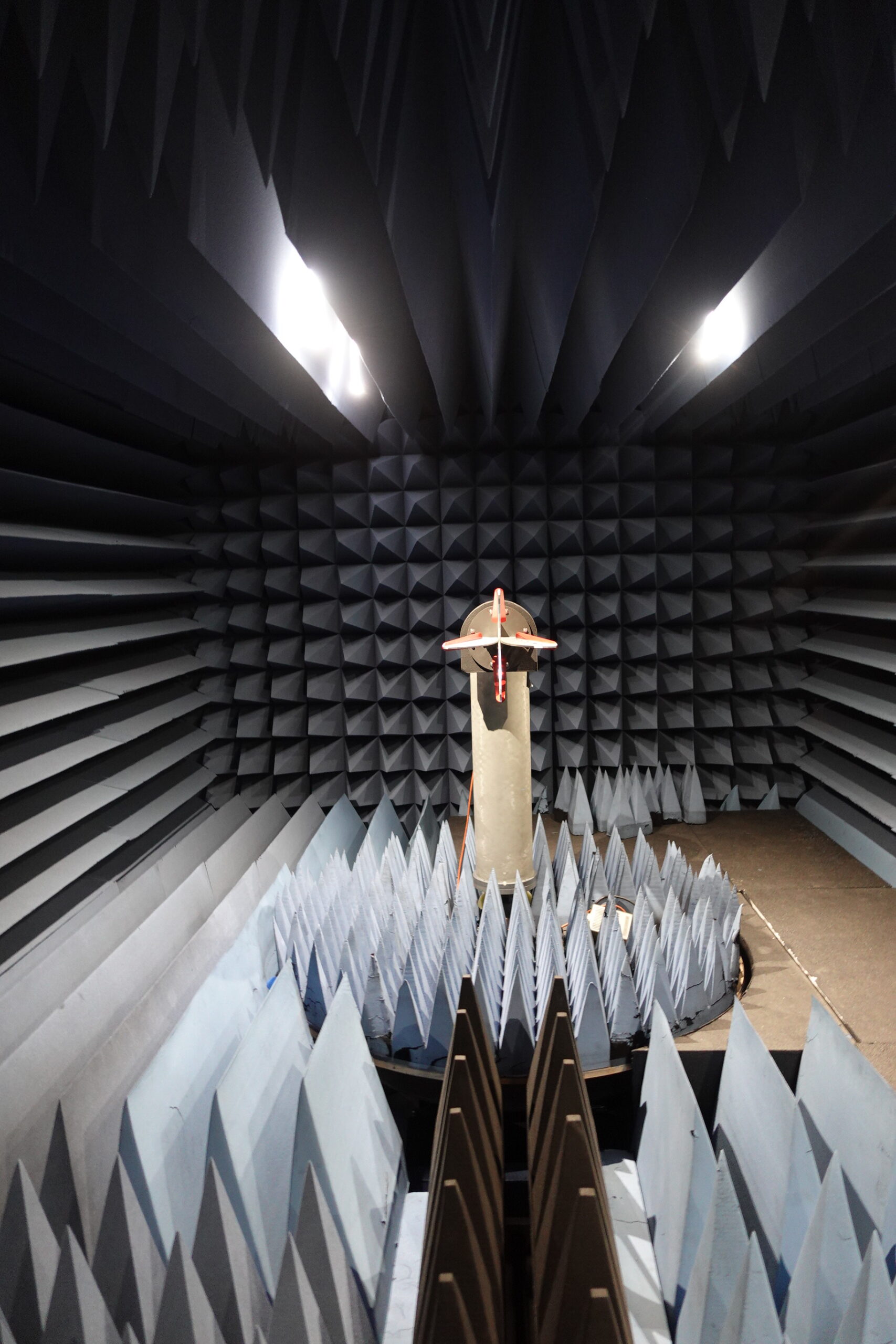
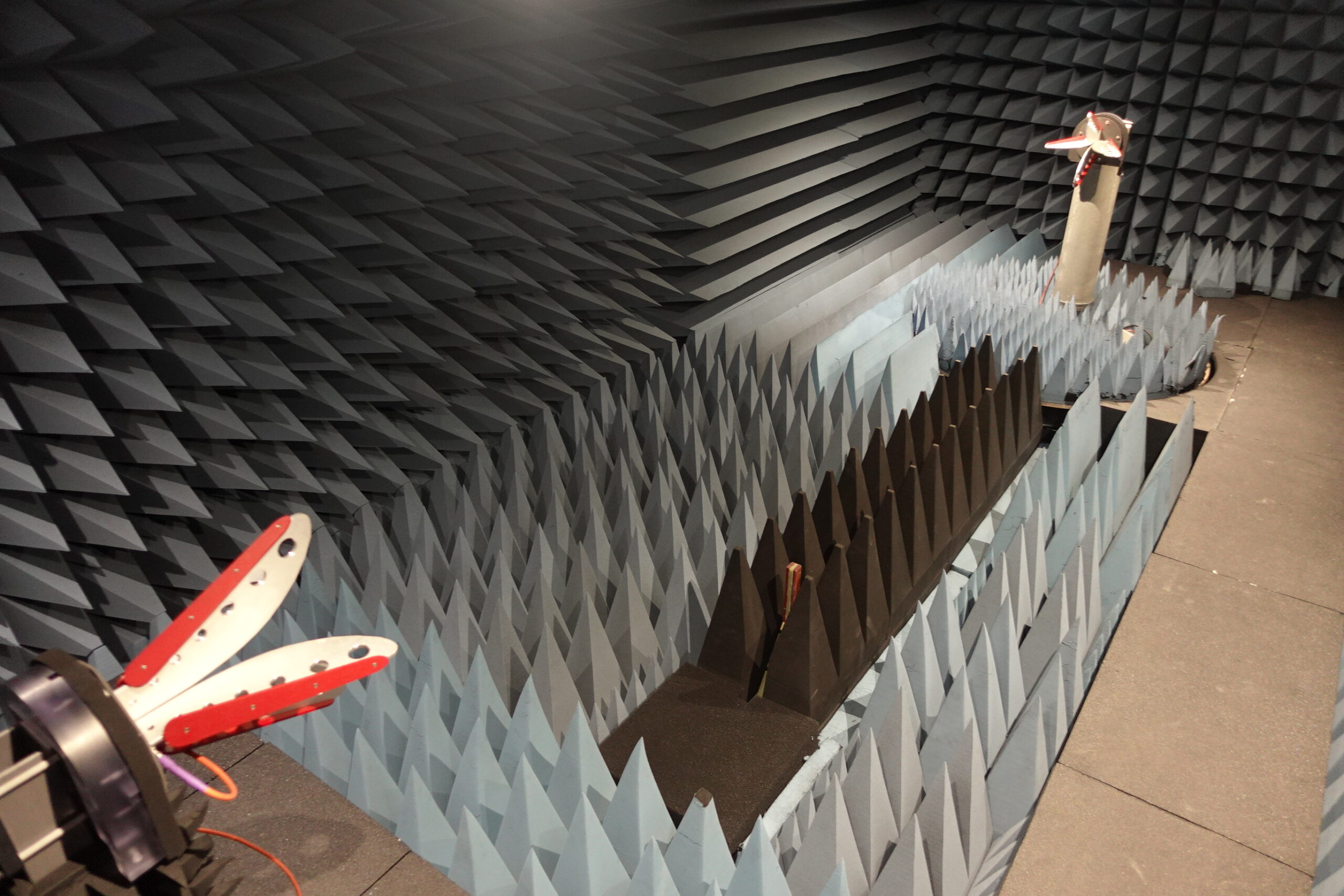
The iEMSL houses a fully Anechoic Chamber and associated equipment to enable antenna characterization measurements from 400 MHz to 140 GHz. The chamber interior measures 24 ft, 10 ft and 6.5 ft in length, width and height. It features a quiet zone with better than 20 dB attenuation using an automated measurement system for RF, microwave and millimeter-wave frequencies. The chamber is located in the Wisenbaker Engineering Building (WEB) room 160.
This facility is currently used to characterize the input match as well as 2D and 3D radiation patterns of the antennas from 400 MHz to 40 GHz.
Chamber Specifications
| Frequency Range | 400 MHz – 140 GHz |
| Chamber Internal Dimensions | 24′ x 10′ x 6.5′ |
| Far Field Distance | 16′ |
| Max AUT weight | 34.0 kg (75.0 lb) |
| Scan Geometry | Two-axis, spherical |
| Scan Range | Up to ±180° pattern coverage |
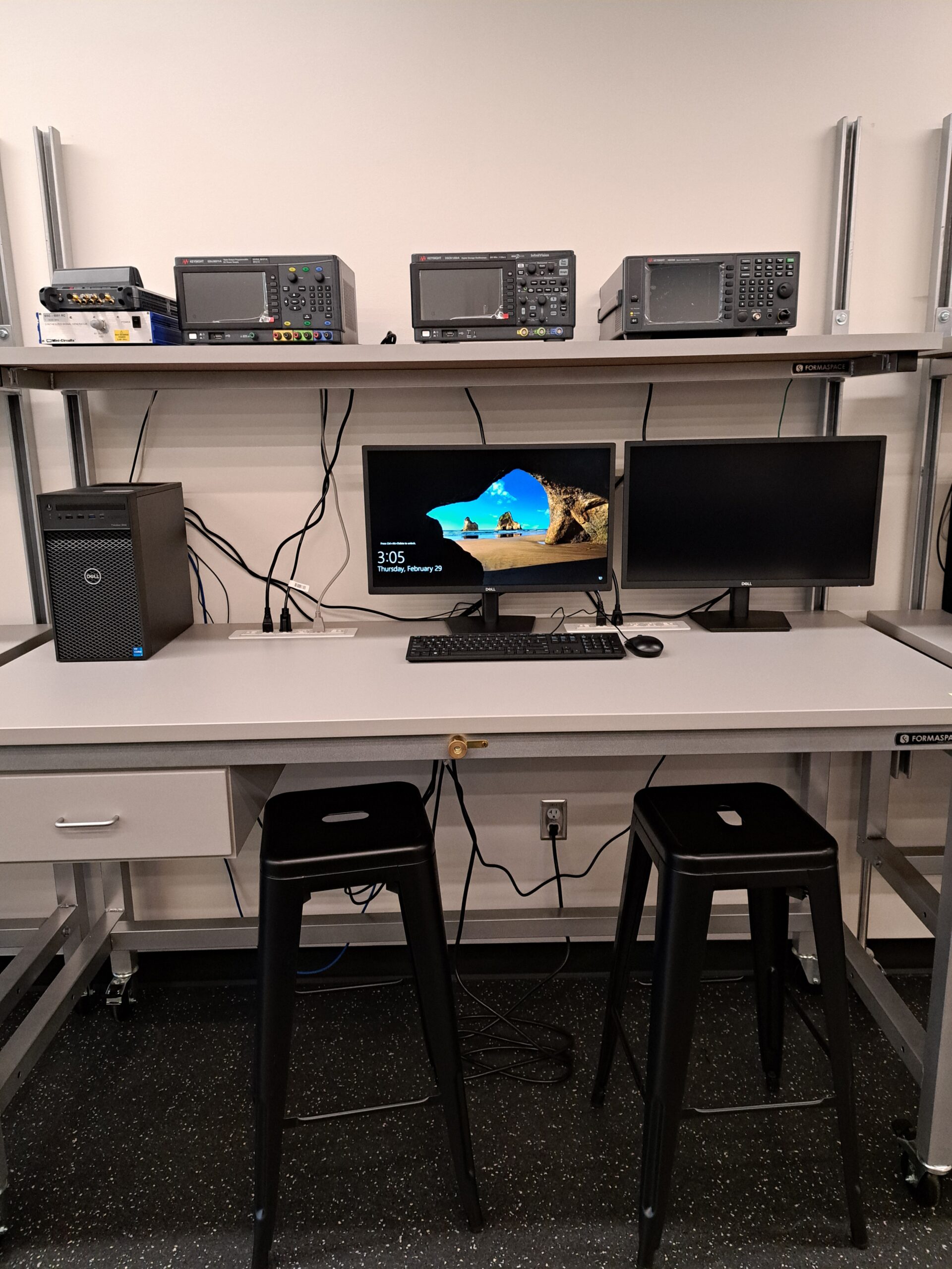
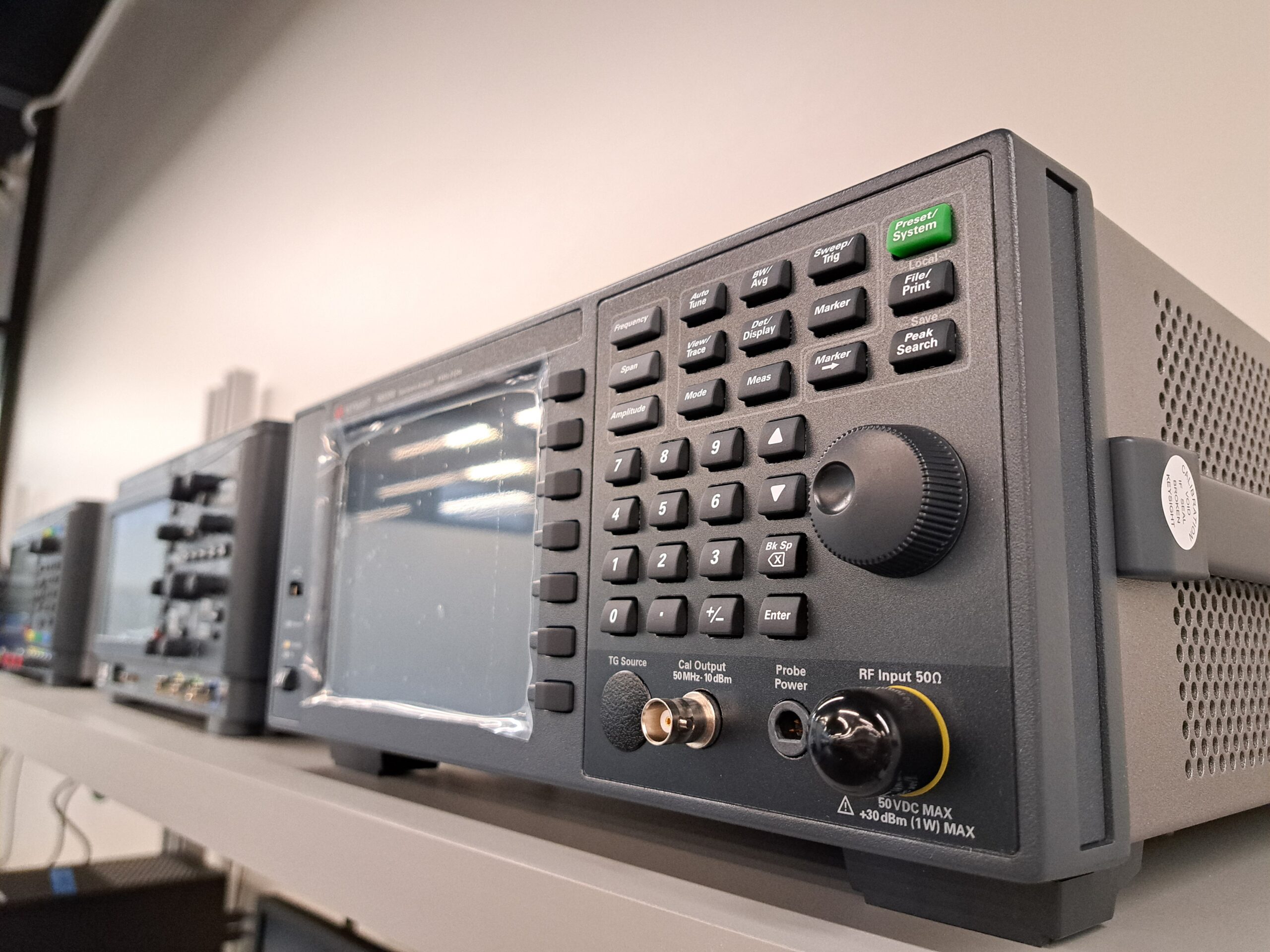
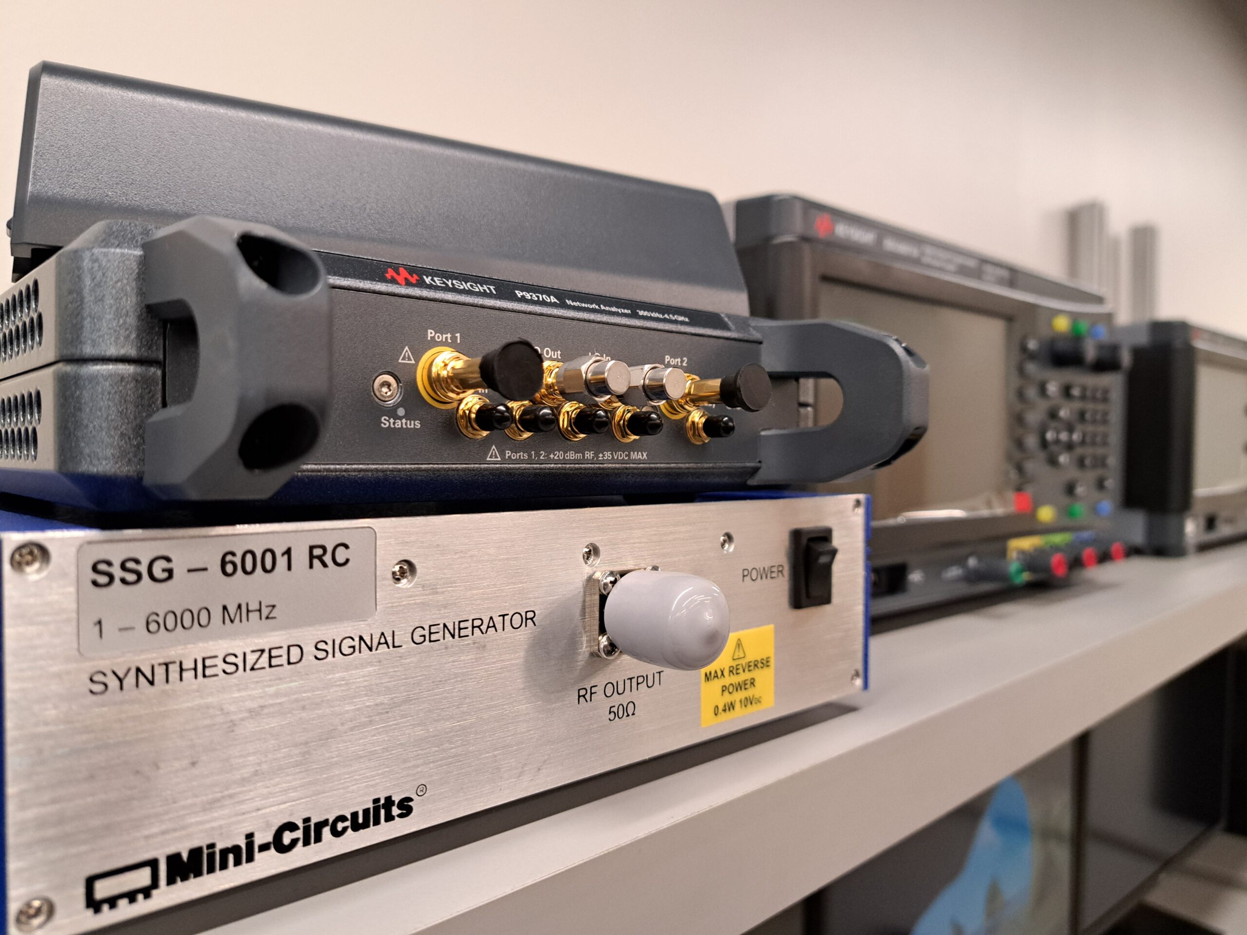
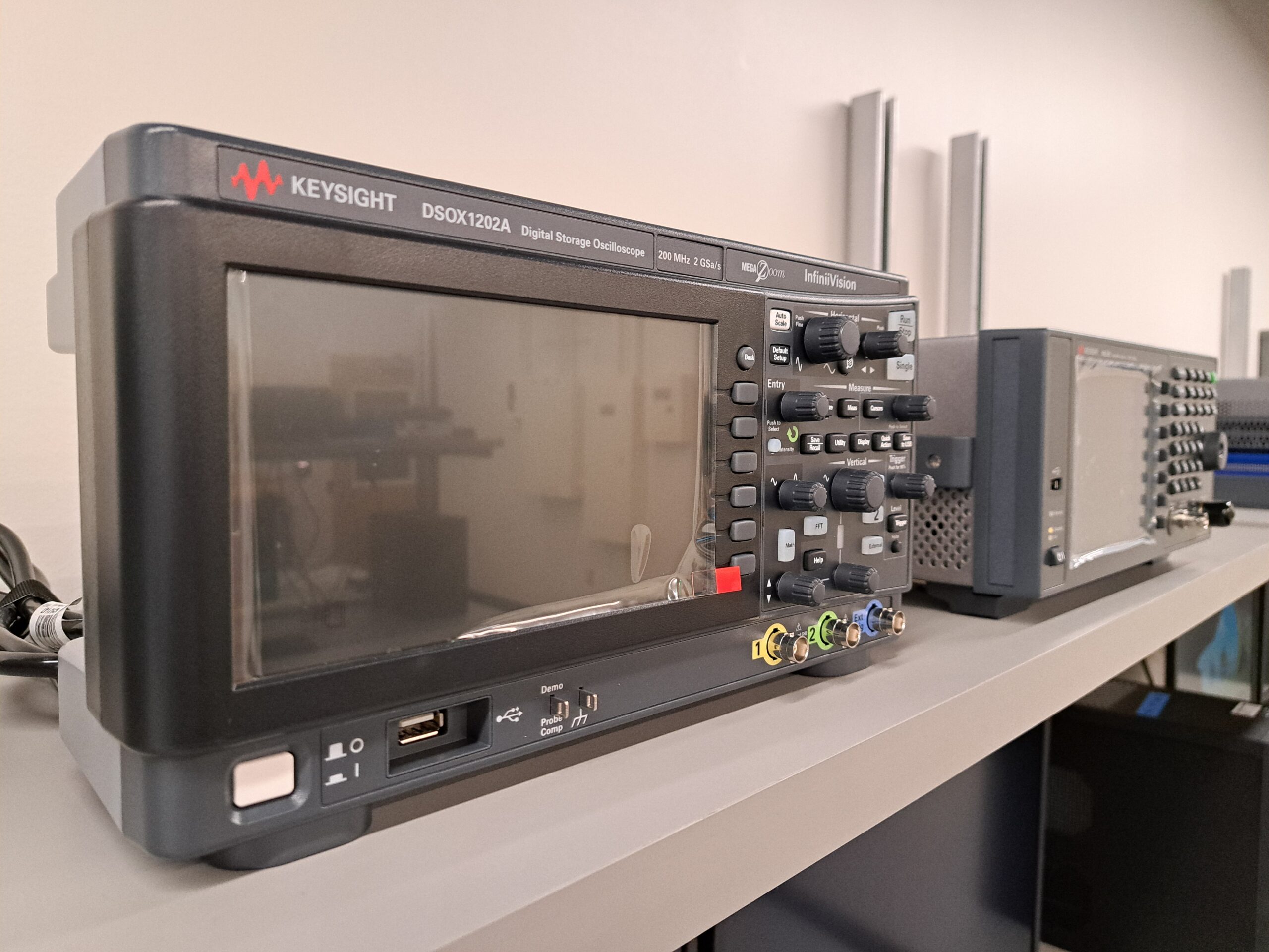
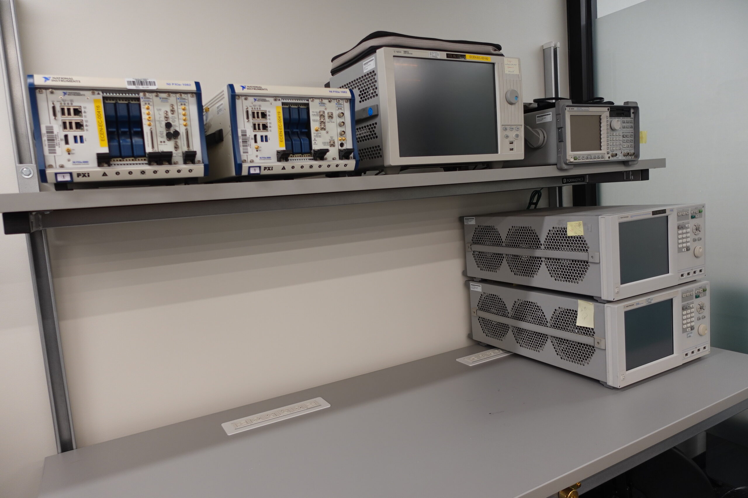
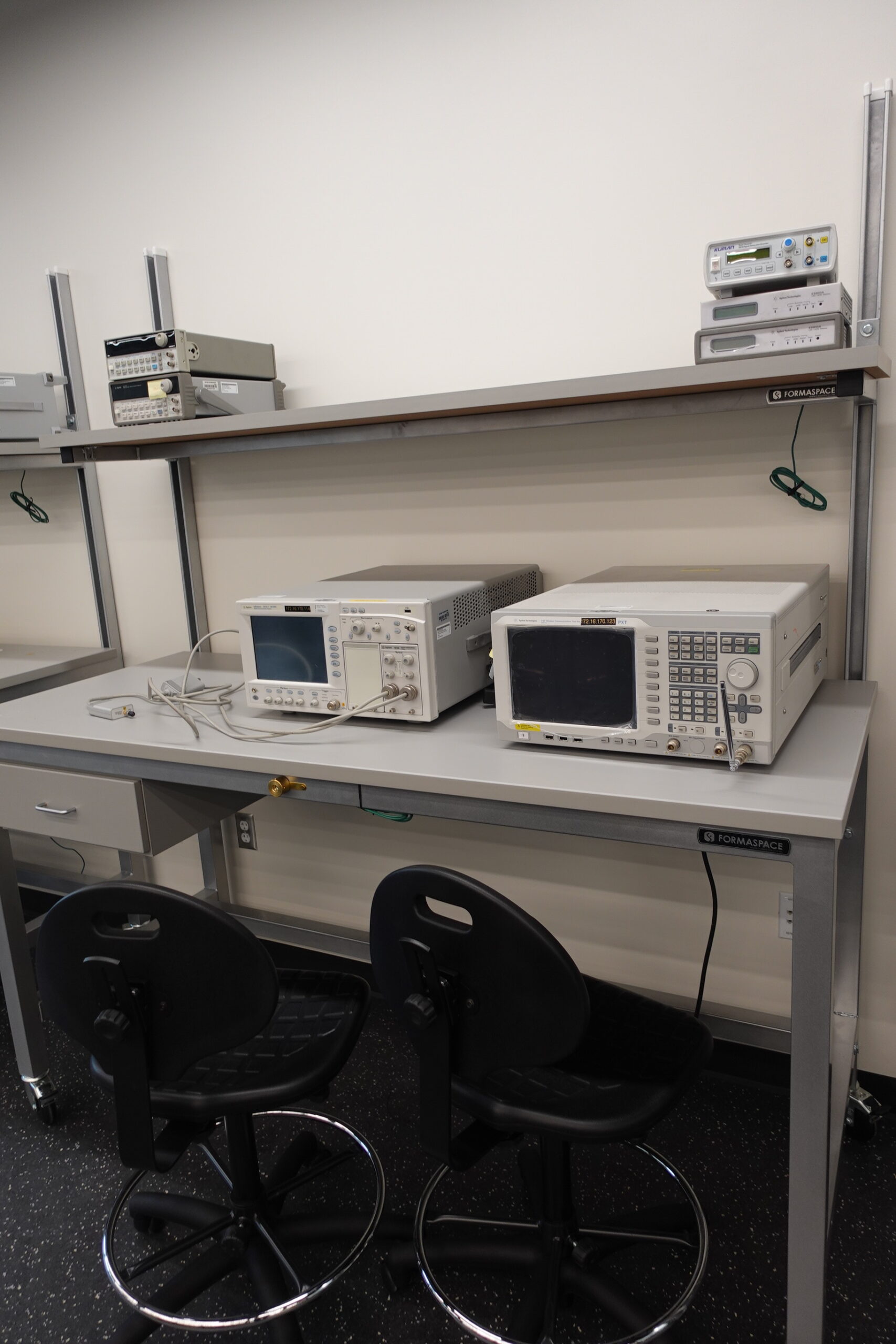
Equipment
- ETS-Lindgren Anechoic Chamber 400 MHz-140 GHz high fidelity measurements
- ETS-Lindgren’s Model 2122 Heavy Duty Multi-Axis Positioning System (MAPS)
- EMCenter™ Modular RF Platform
- EMQuest™ EMQ-100 Antenna Measurement Software
- Keysight PNA N5227A 67 GHz Vector Network Analyzer (4 Port)
- VDI WR10+ 67-115 GHz VNA Extension Module (2 units)
- VDI WR6.5 110-175GHz VNA Extension Module (2 units)
- Standard Gain Horns for Antenna Characterization
- ETS Lindgren 3164-10 400MHz-10GHz,
- ETS Lindgren 3164-05 2-18 GHz,
- ETS Lindgren 3116C 10-40 GHz,
- Quinstar QWH-UPRR00 40-60 GHz,
- Quinstar QWH-EPRR00 60-90 GHz,
- Quinstar QWH-FPRR00 90-140 GHz
- Assorted RF cables, connectors/adaptors, calibration kits
Antenna Measurement Services in Our Anechoic Chamber
Need professional antenna measurement services in an anechoic chamber? Texas A&M’s IEMSL offers contract antenna testing, pattern and gain measurements, and RF characterization.through the iEMSL’s Measurement Services program.